

When I bought the bike Moto Guzzi Breva 750, I didn't pay too much attention to many things, such as the turn signals. Being my first motorcycle I was too excited just to have it and to hear the engine running. I noticed that the turn lights weren't working. More specifically, they were working one time out of ten times of switching. The seller told me that it could be a fuse or the mechanical relay, or a bad electrical connection. I believed him.
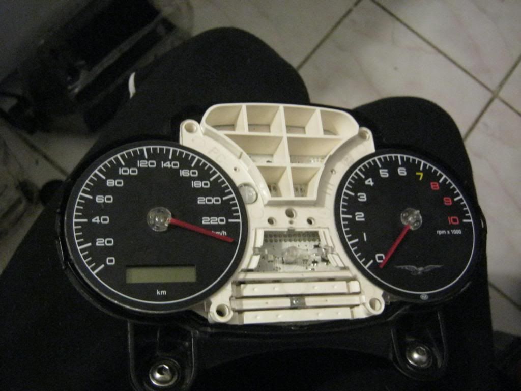
When I arrived home, I realized that the bike didn't even want to start but this story you can see in my previews post. Back to the turn lights - I started to search for the problem. Having too little documentation about the motorcycle at that time, I started by checking the fuses. All the fuses, just to be sure. Then I wanted to check the mechanical relay. Surprise! There were no relay for turn light signals. The next thing I did was to check the path of electrical wiring, to understand the system. I used a DMM for that. The result was that all the wires go to the dashboard. In order to take apart the dashboard, I did a stupid thing because I could not find any info anywhere on the Internet. The PCB just didn't want to take off. So I cut the plastic shell to see inside and to understand how I can remove the PCB. I preferred to destroy the shell, instead of the PCB. The needles (speed&RPM) were the ones that retained the printed plastic with the numbers. So this is very important.
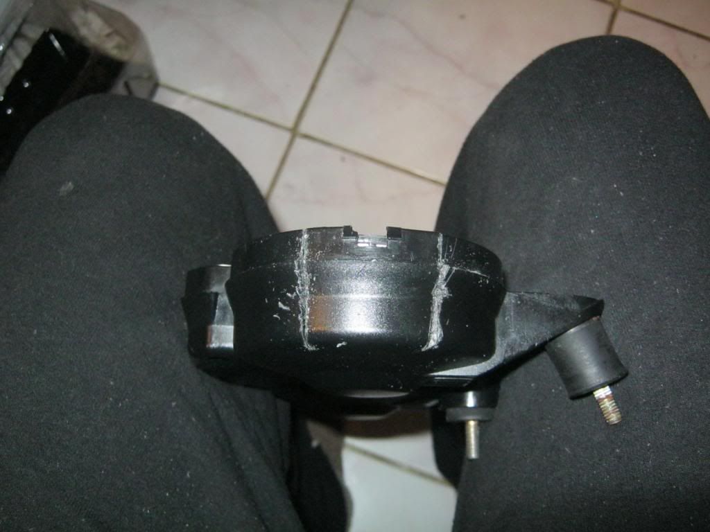
The needles must be pulled out with care.
Then I pasted the shell with Poxipol. Some unsoldering must be done also to get to the PCB.
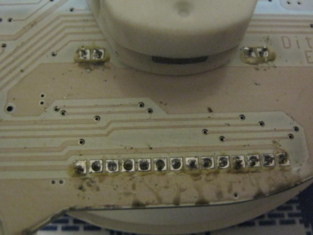
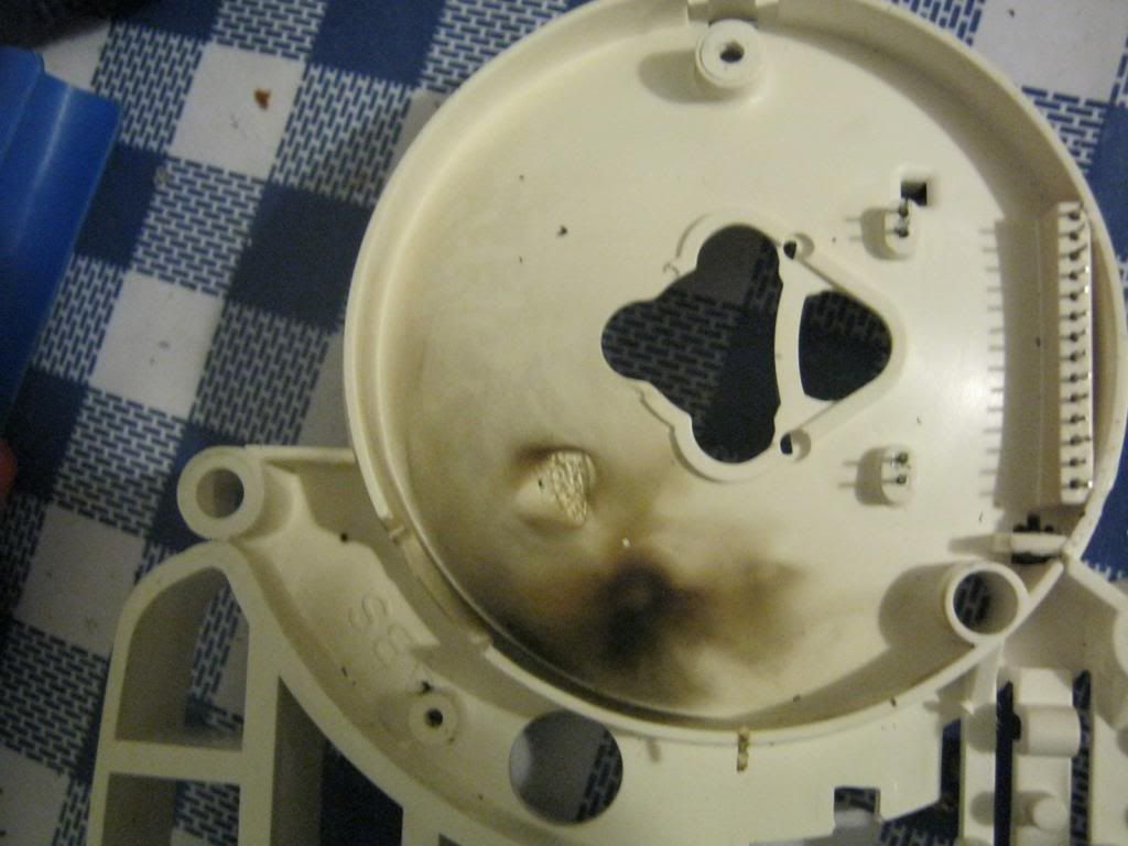
Inside, I had a very big surprise. Before, the PCB had had very big problems. They had apparently not been solved all the way. With the help of the DMM, I succeeded to understand how the turn light system worked.
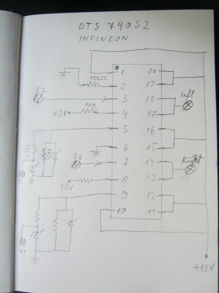
An image can be more than a thousand words, so I made some pictures from my sketches.
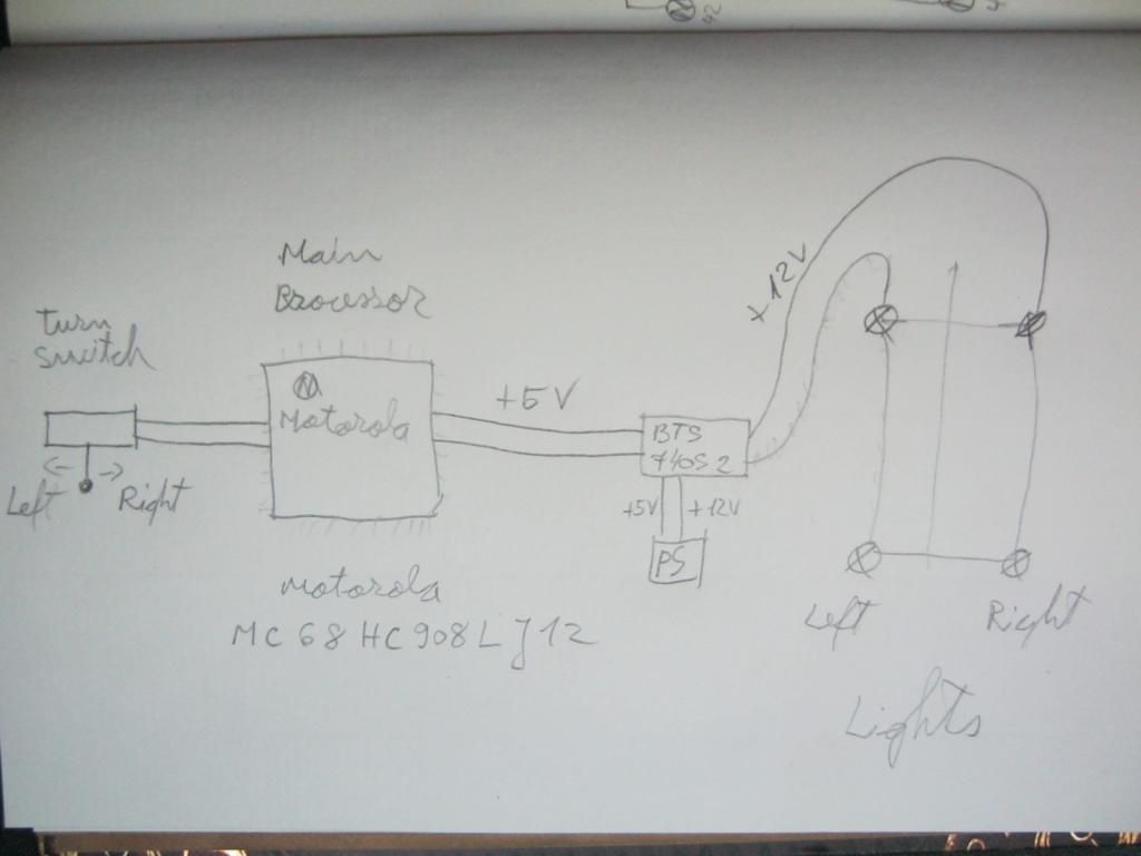
The schematics is simple. There are 5 elements: 1. the handle bar turn lights switch; 2. the main processor - Motorola MC68HC908LJ12 ; 3. the SMD power switch - Infineon BTS 740s2 ; 4. the turn lights ; 5. the power supply (12V and regulated on the board 5V).
Unfortunately I didn't take pictures which include the processor. I didn't know I will write about this.
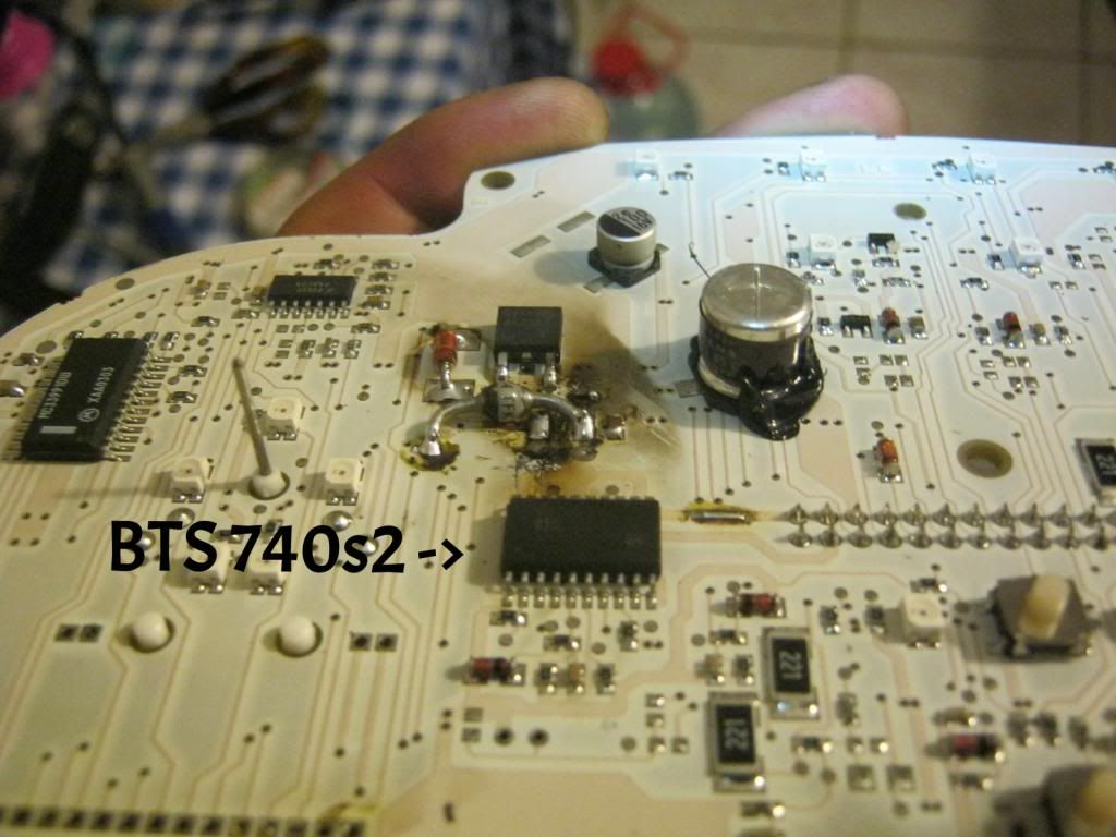
The behavior is simple. When the turn light switch is pushed left or right, the processor senses that and sends +5V to one of the two channel (left or right) of the power switch BTS 740s2. The power switch sends then +12V to the light bulbs. Very simple.
The PCB had a serious problem with the regulated 5V section. Seems like it was some kind of explosion on the board. I think this was a cause for the fail of the power switch.

I hope this post is useful to someone. If you have questions please don't hesitate to comment or to contact me.
Have a nice day and dry roads. :)
Hello Sorin,
ReplyDeleteI read about your repair with great interest because I also have an problem with the turnlight signals. Under 2000 revs it works normal, above 2000 revs the behavior change. I do not understand how revs can influance the turnlight signals so I looked at your schemaś.
I have a question about the first schema. You draw 2 lines from the turnswitch to the microcontroller. How does the microcontroller knows that its left of right? Dit you let the ground (or -) out of the schema?
Ruud
Hi Ruud. Sorry for the low quality of the schematics. I don't exactly remember but there are 3 possibilities for commanding the turn signals. The turn switch either connects to one of the two wires to + , to the ground or to another wire from the microcontroller. But this doesn't matter in your case. The IC BTS 740s2 which powers the turn lights is sensitive to the variation of the voltage. In my opinion, you should check the voltage regulator output to see if it's working properly. Since you're experiencing problems over 2000 rev, it means that you have an excess of voltage from the regulator. If the regulator output is OK, I suggest you replace the IC BTS 740s2. It's just an opinion. Please let me know the solution when you have it.
ReplyDeleteAll the best,
Sorin
Hi Sorin
DeleteThanks for your reply. The schema's are ok and helped me understanding the dashboard and its working. You are right about the switch, I think it connects one of the two ports of the microcontroller with the plus.The switch keep the port to the plus until you push forward and disconnect the port to the plus. Maybe there is a pulldown resister connected the ports.
I began with cleaning the switch on the steering. Not a difficult job and so far (after 100km) it is working ok again.
Like you I feared a problem with the voltage because of the 2000 rpm. I still hope it is not.
I wonder after reading your blog how you assembled your dahsboard after repairing.The dashboard is a weak part of the Breva because of the water that can easily come in.How do you keep the water out?
Ruud
To avoid the water to enter in the dashboard, I used some kind of transparent sanitary silicone. It works great.
DeleteNice post. I was looking like this. Really it is very useful and informative post. Thanks for sharing. Thanks again! for more
ReplyDeleteThe engine operation had some problems with the power switch. You should only perform the series of actions to improve the internal structure.
ReplyDelete